10mm bronze gas operated valve
125mm bronze pneumatic valve

Gas Operated Valves

Walton gas pressure control valves have been specifically designed for the control of refrigerant gas pressures in marine refrigeration and air conditioning systems in which the condenser is cooled by sea water.

The function of the valve is to control the gas pressure within the condensers by either diverting the circulating water overboard or recirculating the water to the pump suction. This in turn controls the temperature of the air-conditioned or refrigerated areas.

The valve operates independently of any outside power source, and externally requires only a small bore pipe connection to the refrigerant sensor.

Description

In operation and before the refrigerant gas reaches its working temperature, the valve re-circulates the full volume of sea water back to the pump suction.


As the refrigerant temperature increases and the gas pressure rises into the valve's control range, the valve starts to move, opening the sea water flow to overboard. This reduces the amount of water being re-circulated. A further rise in refrigerant gas temperature and pressure increases the overboard flow and reduces the re-circulation until at some gas pressure within the overall control range, an equilibrium condition is obtained with constant gas pressure and overboard discharge volume.


Any change of load on the machinery or sea water temperature is compensated for by an adjustment in the volume discharged overboard, maintaining the gas pressure - and hence the air-conditioned areas - within the desired control range.

The valve body is provided with 3 equi-spaced ports extending to flanged connections. A rotor operates over two of the ports to give flows varying from ‘full re-circulation/no overboard flow’ to ‘full overboard flow/no re-circulation’. The rotor is mounted upon a shaft extending through the front cover of the valve. This cover also carries the valve actuator on an integral bracket.


A lever secured to the shaft engages with a spherically ended drive pin. The drive pin is clamped into the control block and onto the control rod.


At one side of the bracket formed on the front cover is mounted a gas cylinder which contains a stainless steel edge welded bellows. The bellows with welded end fittings together with ‘O’ ring forms a 100% gas seal.


The whole internal assembly, actuator, etc. can be withdrawn by removing the front cover nuts and without disturbing the main pipe connections.

Sizes

Walton gas operated valve bore sizes range from 10mm to 200mm diameter.

The maximum flow rates that can be accommodated in each valve size are shown here.

Maximum flow rates in m3/hour

Valve Bore Fresh Water Sea Water

25mm

10

10

40mm

22

16

50mm

35

26

65mm

60

45

80mm

90

67

100mm

100

75

125mm

160

120

150mm

180

180

200mm

400

290

Port configuration

Rotary gas-operated valves can be supplied in any of six possible port configurations (called handings) to suit your preferred pipework layout. This provides great flexibility – the valve can be supplied to suit the pipework, rather than the pipework having to be adapted to suit the valve.

The possible handings are shown on the right:

LI Handing
LB Handing
LC Handing
RI Handing
RB Handing
RC Handing

System design

The valve is designed for installation in the sea water circuit of the refrigerant condenser downstream of the condenser.


The piping is arranged so that the valve can either discharge water overboard, or re-circulate water to the pump suction or proportion the incoming flow of water to both the overboard and re-circulation branches in accordance with the gas pressure in the refrigerant condenser.

To mitigate undue loading on the valve mechanism's main bearings, we would recommend that where possible the valve be installed with its actuator in the upright position.

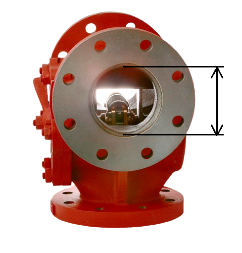
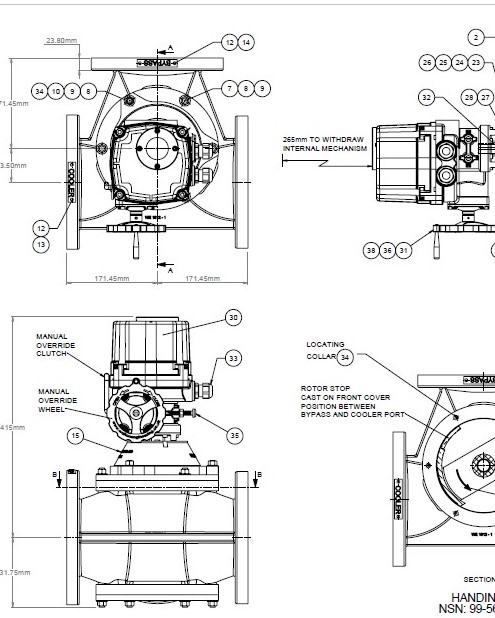
The mounting of the valve should be such that it is not subject to excessive vibrations under running conditions. In positioning the valve, a clear space approximately equal to the valve body length is required to withdraw the rotor and in way of the actuator, spaces equal in length to the gas cylinder and the spring assembly are required for easy dismantling.


A degree of flexibility in at least one of the connecting pipes is desirable although, if care is taken on installation, not essential. Mounting of the valve should be such that it is not subjected to excessive loading or vibration under running conditions. Temperature variations, pipe expansion and movement of the ship's hull should be taken into account when designing the piping runs and supports.


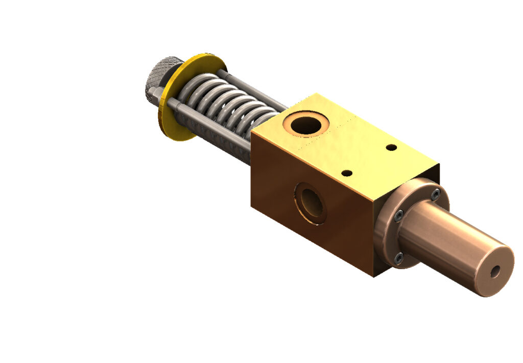
Two tapped holes are provided in the end of the gas cylinder, one for connection to the refrigerant condenser and one spare for bleeding purposes and pressure gauge if required. The connection between the gas cylinder and the refrigerant condenser need be no greater than 1/8" (3mm) bore diameter

Mixing valve
Diverting valve

We are always willing to create a customised solution for your application if none of our standard products are suitable

Our advanced computer aided design software and the flexible nature of the Walton valve design mean that this can often be a cost-effective approach.

Quotation request form